Introduction
IoT is rapidly revolutionizing the healthcare industry. Due to the busy schedule and work of our daily life, it is a difficult task to monitor the health status of our patient at home. Particularly aging patients should be monitored periodically. Therefore we propose an innovative system that easily automates this task. Our device advances a smart patient health tracking system using a web server to monitor patient health parameters such as blood oxygen levels along with heart temperature and body temperature.
Components Required
Following are the components required for making this project. All the components can be purchased
from Amazon. The components purchased link is given below.
from Amazon. The components purchased link is given below.
1. NodeMCU : Buy Online from Amazon
2. MAX30100/MAX30102 Pulse Oximeter: Buy Online from Amazon
3. DS18B20 Temperature Sensor: Buy Online from Amazon
4. DHT11 Sensor: Buy Online from Amazon
5. 4.7K Resistor: Buy Online from Amazon
1. NodeMCU
Node MCU is an open source platform and has a chip of esp8266 wifi module, 128KB RAM and 4 MB flash memory to store the program and data. Its operating system range is 3v to 3.6 and it consists of 17 GPIO pins. It has communication speed 4.5 Mbps.
NodeMCU is a development board based on ESP8266. It is operating system range is 3v to 3.6. Interface a GPS module with NodeMCU. In this project we will use NodeMCU to create a simple local web server and the location details and update in that server web page.

NodeMCU Specification:
Type : Single-board microcontroller CPU : ESP8266Memory : 128kBytesStorage : 4MBytesPower By : USBPower Voltage : 3v ,5v (used with 3.3v Regulator which inbuilt on Board using Pin VIN)IDE Used : Arduino IDEGPIO : 10 pins
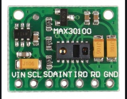
2. MAX30100/MAX30102 Pulse Oximeter
Features:Working voltage: 1.8-5.5V I2C INTERFACE Complete Pulse Oximeter and Heart- Rate Sensor Solution Simplifies Design Integrated LEDs, Photo Sensor, and High- Performance Analog Front - End Ultra- Low- Power Operation Increases Battery Life for Wearable Devices Programmable Sample Rate and LED Current for Power Savings Ultra- Low Shutdown Current (0.7µA, typ) The device has two LEDs, one emitting a red light, another emitting infrared light. For pulse rate, only the infrared light is needed. Both the red light and infrared light is used to measure oxygen levels in the blood.3. DS18B20 Temperature Sensor:
DS18B20 is 1-Wire digital temperature sensor from Maxim IC. Reports degrees in Celsius with 9 to 12-bit precision, from -55 to 125 (+/-0.5). Each sensor has a unique 64-Bit Serial number etched into it - allows for a huge number of sensors to be used on one data bus.Features:
- Unique 1-Wire® interface requires only one port pin for communication
- Each device has a unique 64-bit serial code stored in an onboard ROM
- Power supply range is 3.0V to 5.5V
- Measures temperatures from –55°C to +125°C (–67°F to +257°F)±0.5°C accuracy from –10°C to +85°C
- Thermometer resolution is user-selectable from 9 to 12 bits
- Converts temperature to 12-bit digital word in 750ms (max.)
- Alarm search command identifies and addresses devices whose temperature is outside of programmed limits (temperature alarm condition)
- Applications include thermostatic controls, industrial systems, consumer products, thermometers, or any thermally sensitive system
4. DHT11 Sensor
The DHT11 is a basic, ultra low-cost digital temperature and humidity sensor. It uses a capacitive humidity sensor and a thermistor to measure the surrounding air, and spits out a digital signal on the data pin (no analog input pins needed). Its fairly simple to use, but requires careful timing to grab data. The only real downside of this sensor is you can only get new data from it once every 2 seconds, so when using our library, sensor readings can be up to 2 seconds old.Features:
- Low cost
- 3 to 5V power and I/O
- 2.5mA max current use during conversion (while requesting data)
- Good for 20-80% humidity readings with 5% accuracy
- Good for 0-50°C temperature readings ±2°C accuracy
- No more than 1 Hz sampling rate (once every second)
- Body size 15.5mm x 12mm x 5.5mm
- 4 pins with 0.1" spacing
Working:Now let us begin with the designing of IoT Based Patient Health Monitoring Using NodeMCU. So the circuit digram for interfacing MAX30100, DHT11 & DS18B20 with NodeMCU is given below.All the sensor can work at 3.3V VCC. So connect their VCC to 3.3V Power Supply. Connect the GND to GND. MAX30100 is an I2C Sensor, so connect its SDA & SCL pin to GPIO21 & GPIO22. Connect its INT pin to GPIO19 of NodeMCU. The output pin of DHT11 is connected to GPIO18 of NodeMCU. Similarly, the output pin of DS18B20 is connected to GPIO5 of NodeMCU. A 4.7K pull-up resistor is connected between output pin & VCC pin of DS18B20.Source Code/Program
The Program/Source Code for IoT Based Patient Health Monitoring on ESP32 Web Server is given below. You need to install a few libraries for source code compilation. The library link is given below as well. Download all the libraries and add to the Arduino IDE.Make changes in the Wifi SSID & PasswordClick to below for Source Code⇓⇓⇓⇓⇓⇓⇓⇓⇓Results & Working of the Project
Once the code is uploaded, you can open the serial monitor. The ESP32 will try to connect to a network. Once connected, it will display the IP Address.Copy the IP Address and paste it on any of the Web Browser and hit enter. You will see the room temperature, room humidity, Heart Rate, Blood Oxygen Level, Body Temperature, etc.Similarly you can also view the Patient Health Status on Mobile Phone. Simple copy the IP Address and paste on the browser of Mobile Phone.