1. Introduction
1.1 What is LG01
The LG01 is an open source single
channel LoRa Gateway. It lets you bridge LoRa wireless network to an IP network
base on WiFi, Ethernet, 3G or 4G cellular. LG01 runs on open source embedded
Linux system; it has USB host port and has full Ethernet and 802.11 b/g/n WiFi
capabilities. The USB host port can be used to connect cellular modules so LG01
is very flexible to bridge LoRa Network to different kinds of network to fit
user’s requirement.

1.2 Specifications
Hardware System:
Linux
Part:
Ø 400Mhz
ar9331 processor
Ø 64MB
RAM
Ø 16MB
Flash MCU Part:
Ø MCU:
ATMega328P
Ø Flash:
32KB
Ø SRAM:
2KB
Ø EEPROM:
1KB
Interface:
Ø Power
Input: 9 ~ 24v DC
Ø 2
x RJ45 ports
Ø USB
2.0 Host port x 1
Ø Internal
USB 2.0 Host Interface x 1
WiFi Spec:
Ø IEEE
802.11 b/g/n
Ø Frenquency
Band: 2.4 ~ 2.462GHz Ø Tx power:
ü
11n tx power : mcs7/15: 11db mcs0 : 17db
ü
11b tx power: 18db
ü
11g 54M tx power: 12db
ü
11g 6M tx power: 18db
Ø Wifi
Sensitivity
ü
11g 54M : -71dbm
ü
11n 20M : -67dbm
LoRa
Spec:
Ø Frequency
Range:
ü
Band 1 (HF): 862 ~ 1020 Mhz
ü Band
2 (LF): 410 ~ 528 Mhz Ø 168 dB maximum link
budget.
Ø +20
dBm - 100 mW constant RF output vs.
Ø +14
dBm high efficiency PA.
Ø Programmable
bit rate up to 300 kbps.
Ø High
sensitivity: down to -148 dBm.
Ø Bullet-proof
front end: IIP3 = -12.5 dBm.
Ø Excellent
blocking immunity.
Ø Low
RX current of 10.3 mA, 200 nA register retention.
Ø Fully
integrated synthesizer with a resolution of 61 Hz. Ø FSK, GFSK, MSK, GMSK, LoRaTM and OOK
modulation.
Ø Built-in
bit synchronizer for clock recovery.
Ø Preamble
detection.
Ø 127
dB Dynamic Range RSSI.
Ø Automatic
RF Sense and CAD with ultra-fast AFC.
Ø Packet
engine up to 256 bytes with CRC.
Ø Built-in
temperature sensor and low battery indicator.
Cellular 4G LTE (optional):
Ø Micro
SIM Slot
Ø Internal
4G Antenna + External 4G Sticker Antenna.
Ø Up
to 100Mbps downlink and 50Mbps uplink data rates
Ø Worldwide
LTE,UMTS/HSPA+ and GSM/GPRS/EDGE coverage
Ø MIMO
technology meets demands for data rate and link reliability in modem wireless
communication systems
Cellular 3G UMTS/HSPA+ (optional):
Ø Micro
SIM Slot
Ø Internal
3G/4G Antenna + External 3G/4G Sticker Antenna.
Ø Up
to 14.4Mbps downlink and 5.76Mbps uplink data rates
Ø Worldwide
UMTS/HSPA+ and GSM/GPRS/EDGE coverage
Ø High-quality
data and image transmission even in harsh environment
Ø Primary
and diversity receive paths are designed for equivalent noise-figure
performance
1.3 Features
ü Open
source Linux (OpenWrt) inside. User can modify or compile the firmware with
custom features and own brand.
ü Low
power consumption.
ü Compatible
with Arduino IDE 1.5.4 or later, user can program, debug or upload sketch to
the MCU via Arduino IDE.
ü Managed
by Web GUI, SSH via LAN or WiFi.
ü Software
upgradable via network.
ü Auto-Provisioning.
ü Built-in
web server.
ü Support
internet connection via LAN port, WiFi or 3G /4G dongle.
ü Failsafe
design provides robustly system.
1.4 System Structure

1.5 Applications

1.6 Hardware Variants
There are different LG01 variants for difference
applications. Below table shows the difference between these models.
Model
|
Photo
|
Description
|
LG01-P
|
 |
The most general version can be used as a LoRa Gateway.
|
LG01-S
|
 |
Include screw terminal which can connect to external sensors
|
OLG01
|
 |
Outdoor
version, this version doesn’t include LoRa antenna, instead, it has a SMA
connector, user can connect it to a high gain LoRa antenna.
It can be powered by a passive PoE adapter.
|
1.7 Install SIM card in EC20/UC20 3G/4G module
Please use below direction to install the SIM
card.

2. Quick Start Guide
2.1 Access and config LG01
The LG01 is configured as a WiFi AP by factory default.
User can access and configure the LG01 after connect to its WiFi network.

At the first boot
of LG01, it will auto generate an unsecure
WiFi network call dragino2-xxxxxx
User can use the laptop to connect to this WiFi
network. The laptop will get an IP address 10.130.1.xxx and the LG01 has the
default IP 10.130.1.1
Open a browser in the laptop and type 10.130.1.1 User
will see the login interface of LG01.
The account for Web Login is:
User Name:
root
Password:
dragino

2.2 Program
microcontroller.
The MCU (microcontroller) M328P is used to communicate
with LoRa Radio part and Dragino Linux module. The program language for the MCU
is based on C and program tool is Arduino IDE.
Below the way shows how to do program it.
2.2.1 Download and configure Arduino IDE
Ø Download
the latest Arduino Software(IDE) from Arduino official site: https://www.arduino.cc/en/Main/Software
Install the IDE in the PC, open it and click File -->
Preference, add below URL
http://www.dragino.com/downloads/downloads/YunShield/package_dragino_yun_test_index.json
in the Additional
Boards Manager URLs.

Ø Go
to tools
--> Boards --> Boards Manager, find Dragino boards info and
install it.

Ø After
install Dragino’s board info in the IDE, we can see the boards info from the
IDE, as below screenshot. For LG01, we should choose: Dragino Yun-UNO or LG01/OLG01.

Note: If user has trouble to install via Board
Manager. User can manually add the board
profile.
2.2.2 Upload a sketch in the MCU
For the very start, we can try to upload a simple
sketch to the MCU and see how it works.
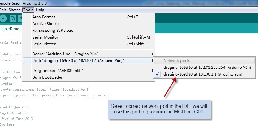
Ø Make
sure your computer and the LG01 is in the same network, if you already connect
to the LG01 WiFi SSID, then both devices are in the same WiFi network. In the
IDE, select the correct port as below screenshot.
Ø Select
the example from IDE --> File --> Examples --> Dragino --> Basic -->
Blink
Click Upload to upload the sketch to LG01, the LG01
may ask you password to upload, if so, type the password of LG01.

Ø Check
result
The blink sketch will set the A2 pin of the MCU to
periodically high and low. This pin connects to the HEART LED of the LG01. So if
successfully upload this sketch, user can see the HEART LED turn on and turn off
periodically.
2.3 Simple LoRa wireless example
To test LoRa wireless, we at least need 2 devices both
support LoRa. In this example we will use below devices:
ü LoRa
Gateway: LG01 ;
ü LoRa
Client: LoRa Shield + Arduino Uno

In this example, we will show the basic LoRa
Communication: The LoRa Client will broadcast a data via LoRa wireless, the
LG01 gateway will get this data and show the data in the PC.
2.3.1 Installing LoRa Library
The Library used here for LoRa communication is called
Radiohead; our sketch will use this library so we need to download it
from:
https://github.com/dragino/RadioHead/archive/master.zip. Unzip and put it in
the Arduino Library Folder, the final location looks as below:

To make sure the library is installed corrected, we can
restart the Arduino IDE and see if we can find it in the example code, as shown
below:

2.3.2 Upload Sketch to LoRa Client
a) In
the Arduino IDE, first choose Dragino Yun – LG01,

b) Then
choose the example: LoRa_Simple_Client_Arduino

c) In
the window of LoRa_Simple_Client_Arduino,
choose the board Arduino UNO which is the correct board for LoRa Shield +
UNO:

d) Unload
the LoRa_Simple_Client_Arduino
example sketch to LoRa Shield + UNO via the USB com port. And then
open serial monitor to see the output.
2.3.3 Upload Sketch to LoRa Gateway LG01
a) Click
the Arduino.exe to open another new instance. It is very important to open a
new instance so we can two serial monitor, one for LoRa Client and one for
LG01.

b) In
this new instance, Select LG01 board in Arduino IDE and choose the example LoRa_Simple_Server_Yun

c) Upload
this Sketch to the LG01, then open the serial monitor to monitor the LG01
status.

2.3.4 Analyze Test Result
Below screenshot shows the result of this example.
ü The
Upper window shows the LoRa Client keep sending the LoRa packet out, and wait
for the reply of this packet.
ü The
lower window is from LG01, which shows LG01 get a “Hello World” packet via
LoRa, after LG01 get the “Hello World” packet, it will sent a broadcast LoRa
packet “And hello back to you”, the LoRa Client will then receive it and print
it on the serial monitor.

Notice: in the example
code, the LoRa client will broadcast LoRa Packet once power on. But the LG01
will only receive the LoRa packet and response after the serial monitor of LG01
is opened, the reason is we have this code
while (!Console) ; // Wait for console port to be available which mean the program will loop here until
we open the serial monitor.
It is possible to use another LG01 as
LoRa Client:
Method is same as above, but the example sketch is:
IDE --> File --> Examples --> Dragino -->
LoRa --> LoRa_Simple_Client_Yun
No comments:
Post a Comment